
Why do we need security on wearable devices? The primary reason comes from the fact that, being in direct contact with the user, wearable devices have access to very private and sensitive user’s information more often than traditional technologies. The huge and increasing diversity of wearable technologies makes almost any kind of information at risk, going from medical records to personal habits and lifestyle. For that reason, when considering wearables, it is particularly important to introduce appropriate technologies to protect these data, and it is primary that both the user and the engineer are aware of the exact amount of collected information as well as the potential threats pending on the user’s privacy. Moreover, it has also to be considered that the privacy of the wearable’s user is not the only one at risk. In fact, more and more devices are not limited to record the user’s activity, but can also gather information about people standing around.
This blog post presents a flexible privacy enhancing system from its architecture to the prototyping level. The system takes advantage from anonymous credentials and is based on the protocols developed by M. Chase, S. Meiklejohn, and G. Zaverucha in Algebraic MACs and Keyed-Verification Anonymous Credentials. Three main entities are involved in this multi-purpose system: a main server, wearable devices and localisation beacons. In this multipurpose architecture, the server firstly issue some anonymous credentials to the wearables. Then, each time a wearable reach a particular physical location (gets close to a localisation beacon) where it desires to perform an action, it starts presenting its credentials in order to ask the server the execution of that a particular action. Both the design of the wearable and the server remain generic and scalable in order to encourage further enhancements and easy integration into real-world applications; i.e., the central server can manage an arbitrary number of devices, each device can posses an arbitrary number of credentials and the coverage area of the localisation system is arbitrarily extendable.
Architecture
The complete system’s architecture can be modelled as depicted in the figure below. Roughly speaking, a web interface is used to manage and display the device’s functions. Each user and admin access the system from that interface.
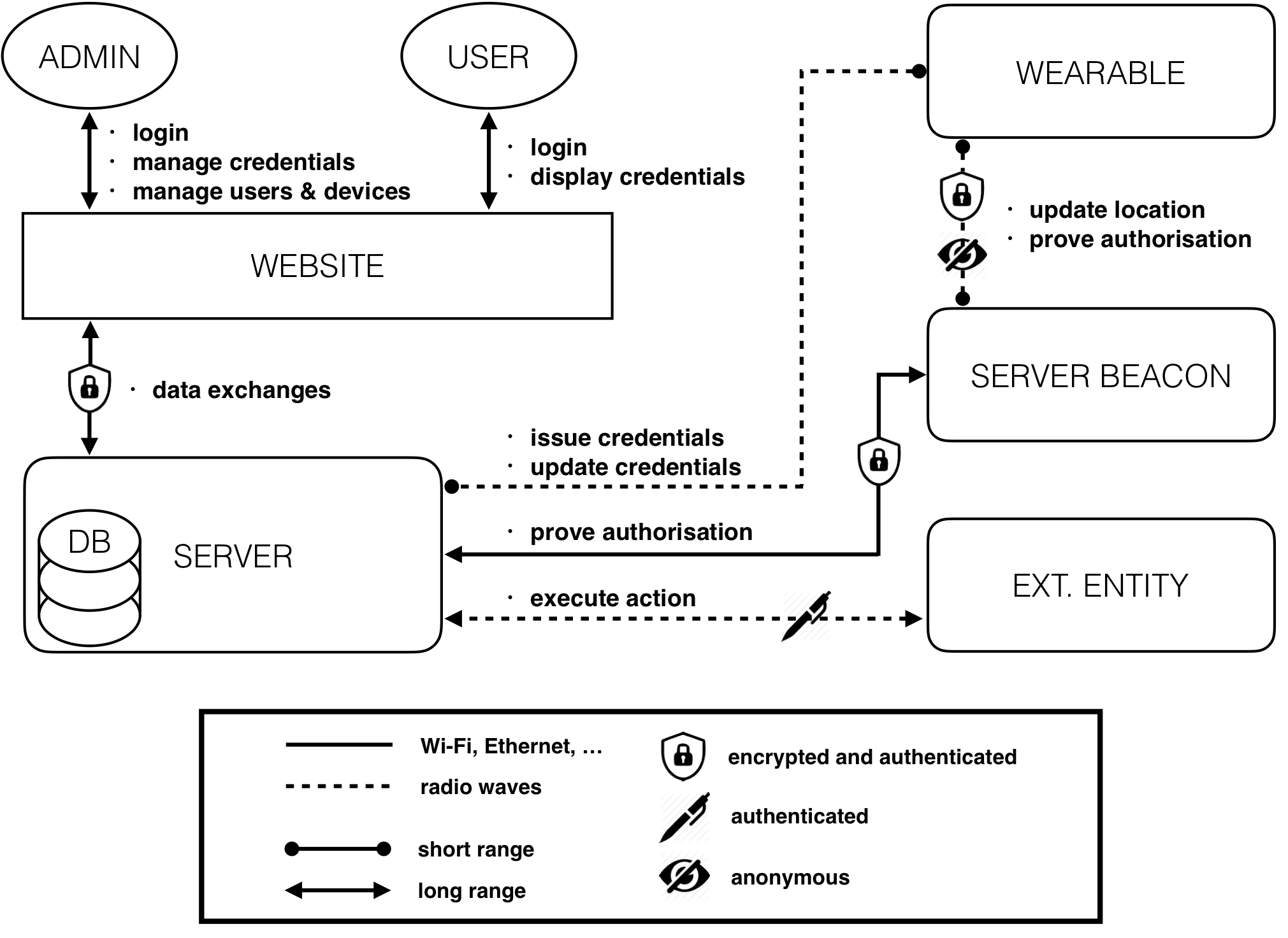
During the setup phase, the server issues the credentials to a selected device (according to the algorithms presented in Algebraic MACs and Keyed-Verification Anonymous Credentials) granting it a given privilege level. The credentials’ issuance is a short-range process. In fact, the wearable needs to be physically close to the server to allow the admins to physically verify, once and for all, the identity of the wearables’ users. In order to improve security and battery life, the wearable only communicates using extremely low-power and short-range radio waves (dotted line on the figure). The server beacons can be seen as continuities of the main server and have essentially two roles: the first is to operate as an interface between the wearables and the server, and the second is to act as a RF localisation system. Each time the wearable granted with enough privileges reaches some particular physical location (gets close to a localisation beacon), it starts presenting its credentials in order to prove to the server that it possesses credentials over some attributes (without revealing them), and that these credentials have been previously issued by the server itself. Note that the system preserves anonymity only if many users are involved (for each privilege level), but this is a classic requirement of anonymous systems. Finally, once the credentials have been successfully verified by the server, the server issues a signed request to an external entity (which can be, for instance, an automatic door, an alarm system or any compatible IoT entity) to perform the requested action.
A concrete example of utilisation of this systems could be associating the external entity to an automatic office door. Therefore, each employee working on that office possesses a wearable with the credentials to access it. Subsequently, when an authorised employee steps close to the door, the device automatically detects its position, knows it is close to the door, and correctly presents the credentials to the server. Then, after credentials’ verification, the server opens the door. Note the usability advantage of having such common operations executed automatically and based on the location; i.e, the user does not even need to present a smart card since the wearable reacts by its own.
Prototype
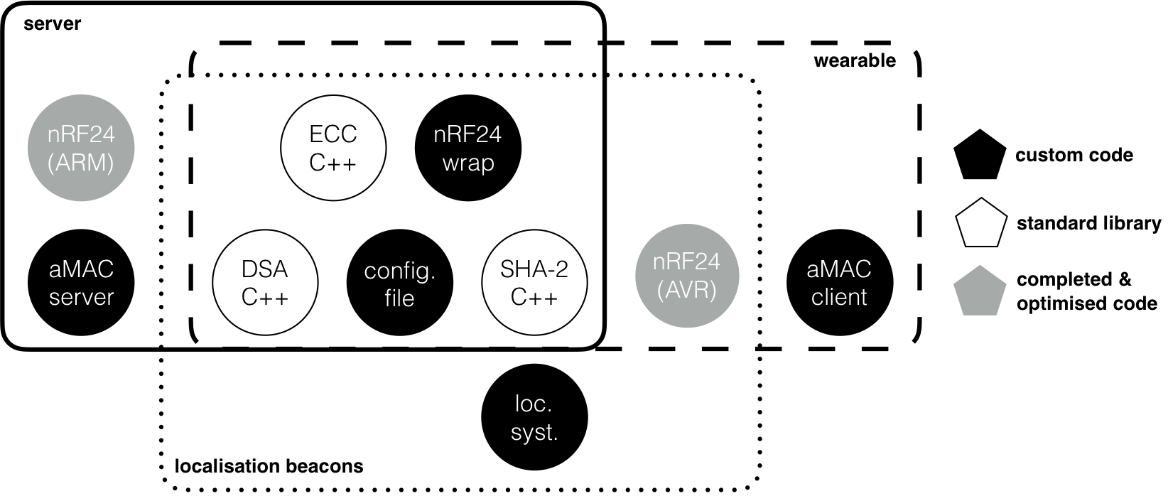
Despite all the blocks and interactions described above are essential to ensure a fully industrial system, the prototype had to be realised with some simplifications due to hardware limitations. More specifically, the first difference involves the wearable-beacon communication: the transmission is signed but not encrypted. Moreover, the server-beacon’s communication is also left unencrypted and the web interface could not be tested on the system’s server. Finally, the prototype communicates entirely through 2.4GHz radio waves.
The server’s prototype has been realised around a Raspberry Pi B+ and the other entities are based on an unofficial Arduino UNO board. Moreover, the server, the wearables and the localisation beacons possess a nRF24 module allowing them to communicate with other entities using 2.4GHz radio waves. This module is based on the standard nRF24l01+ chip which is a great trade off between performance, range, low power and cost. From the software perspective, the prototype is based on many different building blocks, some coming from standard and well-tested libraries while others had to be completely built from scratch. Please note that each module considers 32-bit data type and is only for prototyping purpose (not cryptographically secure).
The FSM below completely illustrates the server’s software behaviour. Once the server is turned on, it starts by initialising all its modules and peripherals. Then, it issues the targeted credentials and enters in a main loop. This loop runs forever and its purpose is to detect when the server needs to react. In fact, the main loop is waiting for the reception of a sync packet addressed to the server’s RX address. Then, if the sync indicates a wearable is willing to show its credentials, the server verifies them and if the verification succeeds, it contacts the external entity. Similarly, when the server is pinged, it answers with a pong packet. The next FSM illustrates the wearable’s behaviour.
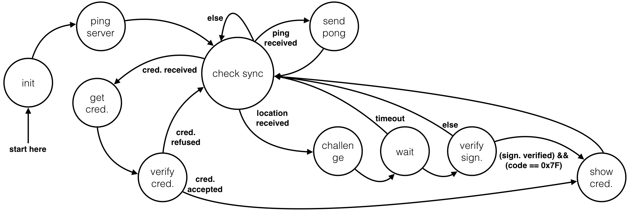
When the wearable is turned on, it starts by testing the connection with the main server by pinging it. Once a sync packet indicates the credentials’ issuance process, the wearable leaves the main loop, gets the credentials and verifies them: if the verification succeeds, it tests immediately the new credentials. Similarly, when a new location is received, the wearable challenges the beacon, and if the location is legitimate, it starts the credentials’ showing phase. The wearable’s software had to be massively optimised in order to fit the very limited Arduino’s resources. For instance, one of the main optimisations was to play with the program and dynamic memory.
The beacon’s software FSM is simpler than the previous one. ![]() Indeed, after the initialisation phase, the beacon enters in a main loop where it sends a location sync packet and then waits for a wearable to answer. If an answer is received, the beacon computes a DSA signature from the hash of the challenge and its location code. Afterwards, the FSM gets ready to play as interface between the wearable and the server for a possible credentials’ showing process. If the wearable decides to presents its credentials, the beacon transfers them to the server and then waits for an ack to pass back to the wearable.
Indeed, after the initialisation phase, the beacon enters in a main loop where it sends a location sync packet and then waits for a wearable to answer. If an answer is received, the beacon computes a DSA signature from the hash of the challenge and its location code. Afterwards, the FSM gets ready to play as interface between the wearable and the server for a possible credentials’ showing process. If the wearable decides to presents its credentials, the beacon transfers them to the server and then waits for an ack to pass back to the wearable.
The embedded system’s memory has two main parts: the program memory and the dynamic memory. The first one is what limits the size of the code, while the dynamic memory is what actually consists in the device resources during execution. The table below reports the exact memory usage of the wearable device and of the localisation beacons (about 5 KB of program memory are due to the boot loader). A special focus has been given to the wearable and the beacons, since they are the entities requiring the most delicate optimization.
| Program memory | Dynamic memory | |
|---|---|---|
| Wearable | 20.080 KB | 284 B |
| Localisation Beam | 14.422 KB | 196 B |
The prototype has been engineered to work in four mode of operation (0x00, 0x01, 0x02, 0x03), allowing the system to trade higher power consumption for better reliability and data-rate. An approximation of the system’s power consumption is provided below.
| nRF24 Operation Modes | Server | Wearable & Beacon |
|---|---|---|
| 0x03 | ≤ 1.062 W | ≈ 143.21 mW |
| 0x02 | ≤ 1.051 W | ≈ 132.40 mW |
| 0x01 | ≤ 1.044 W | ≈ 125.35 mW |
| 0x00 | ≤ 1.041 W | ≈ 122.64 mW |
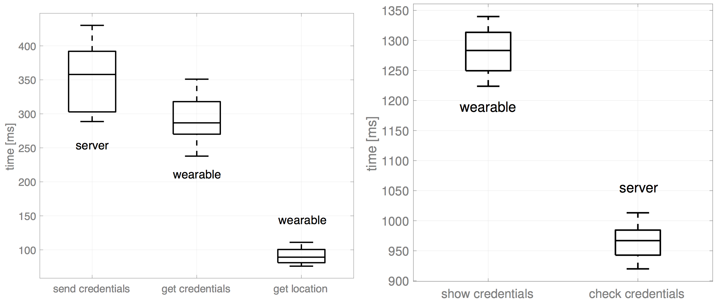
Next, the system latency was tested at room temperature (25 °C) and placing the server and the wearable three meters apart. The figures below show that the credentials’ presentation is by far the slowest process.
 Similarly to the previous analysis, we observe the variation of the error rate (computed as the percentage of the number of failures divided by the number of successes) with the module’s distance for each nRF24’s mode of operation. The dots on the graphs represent the experimental data and the dotted lines are a cubic splines interpolation. The splines show a quasi exponential relation between the error rate and the operational range.
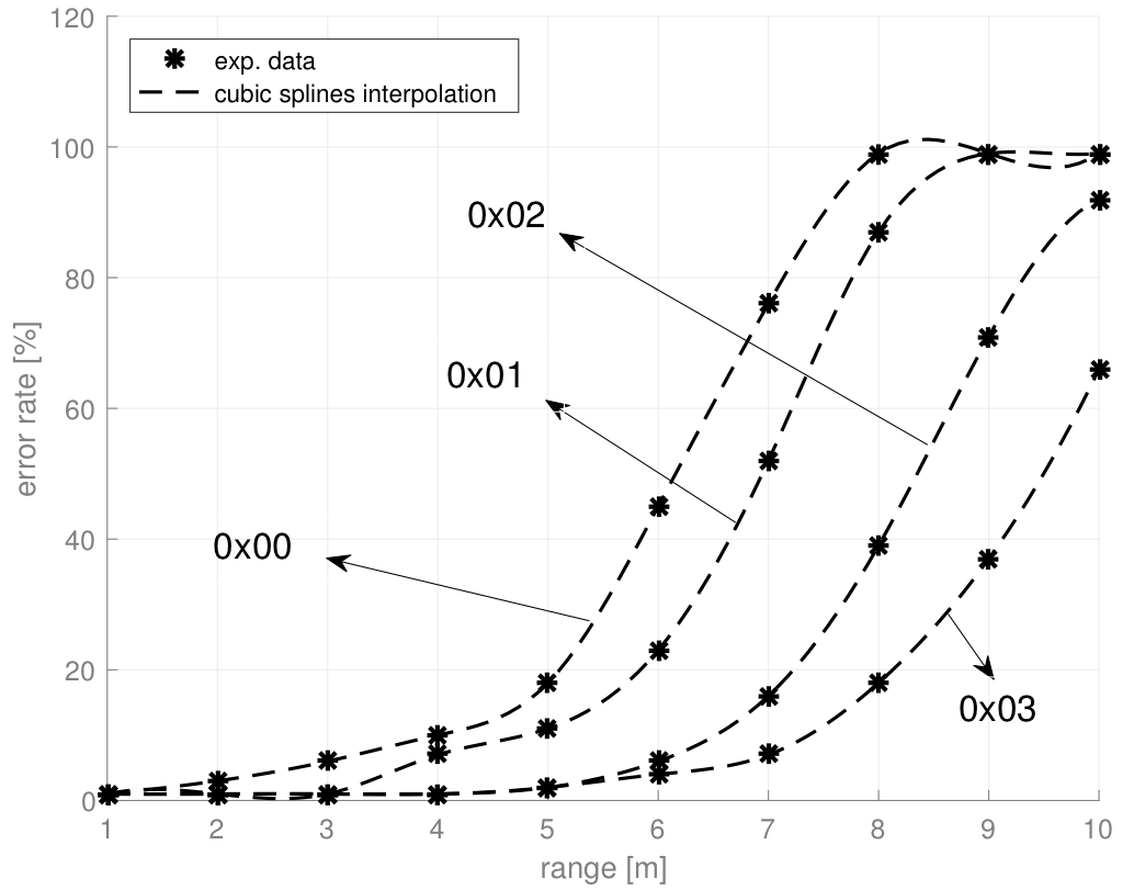
The next analysis is about the system’s temperature dependency. For that experiment, the wearable has been placed into an oven to experimentally test its temperature dependence. The graph shows that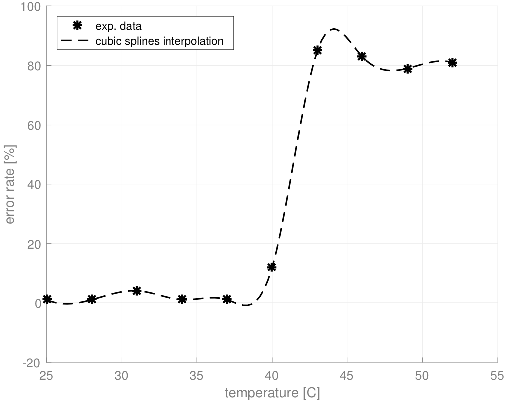 the system is completely stable until about 38C and then the error rate suddenly increases. However, in theory, the wearable should work correctly until 85C since each IC has been manufactured for such conditions.
This huge performance difference could be explained by the fact that despite all the chips have been designed to withstand such temperatures, the other (cheap) components composing the board are not. Indeed, the following well-known facts are always applicable:
- The resonator’s frequency may derive and not produce the exact value (16 MHz);
- IO protocols like I2C and SPI may perform badly;
- Resistors may not produce the exact value (may change up to 8%);
- The jumpers’ resistivity increases with temperature;
- Capacitors may not produce the exact value (may change by a lot more than 8%).
The first and the last point are the most problematic. Indeed, the resonator regulates the CPU operations and the role of the capacitors in the Arduino board are to smooth the signals arriving to the CPU. If these operations are poorly performed, the CPU’s behaviour may become unpredictable.
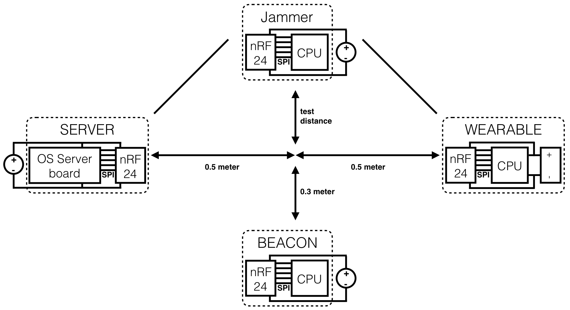
The last graph aims to analyse the system’s sensitivity to radio interferences in order to test the system’s resistance to trivial DoS (jamming). The graph shows a critical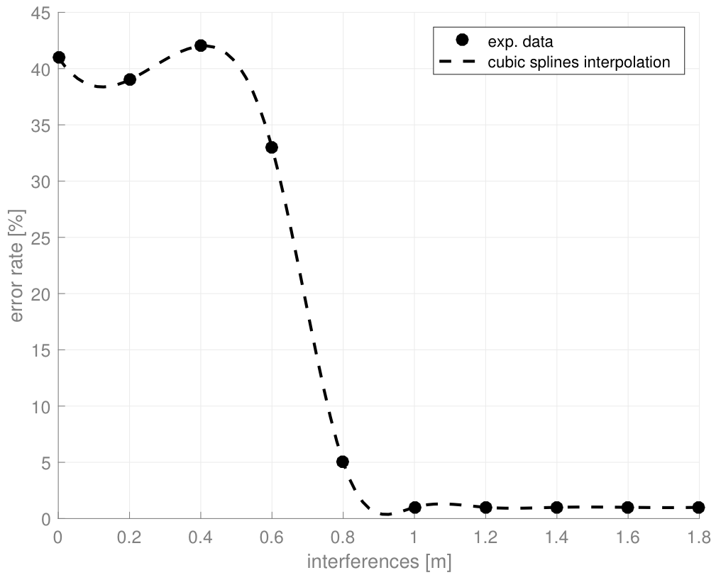 point at around 0.7 m. Indeed, the system seems sensitive to jamming only when the jammer is situated at less than 0.7 m from the median formed by the transceivers. In fact, once this this critical point is reached, the system appears to be immune to interferences. Moreover, even when the jammer is placed right in between the two transceivers (at position 0), the error rate does not exceed 45%. This experiment has been run with the setup below and each transceiver were set to the power mode 0x01.
As usual, the test has been run at room temperature and under the same success’ conditions as in the previous paragraphs.
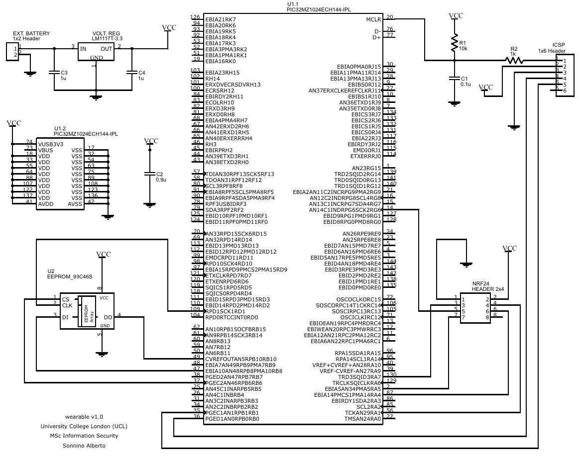
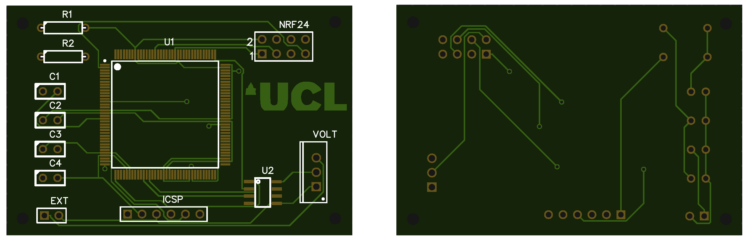
Finally a Printed Circuit Board (PCB) for an industrial application of the discussed wearable device is presented. the industrial wearable could be implemented around a Microchip PIC32MZ microcontroller. In particular, the PIC32MZ1024ECH144 has been chosen because, in addition of coming in a LQFP package (which is relatively easy to solder), it is a good trade off between price, size and performances. However, the presented PCB remains compatible with any LQFP package of PIC32MZ0512EC(E/F/K)144, PIC32MZ1024EC(G/H/M/E/F/K)144 and PIC32MZ2048EC(G/H/M)144. The full schematic of the design is depicted below along with a preview of the PCB’s front and back side, as it would come after manufacturing.
Further details on the architecture and on the prototype, as well as the security analysis and some potentials attacks against the system can be found in my MSc thesis.